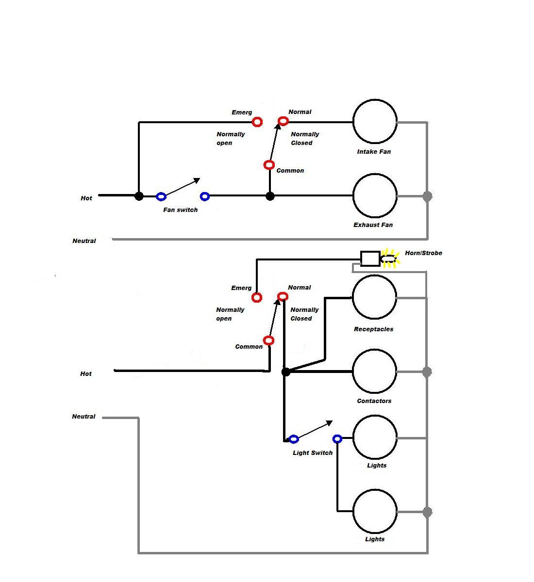
Are you searching for a Ansul System Wiring Diagram? Here you can find info about the Ansul System Wiring Diagram, pointers, and frequently asked questions. We made this page for people searching for a Ansul System Wiring Diagram. Our info will assist you to solve your issue.
A wiring diagram will certainly show you where the cables should be attached, removing the requirement for guesswork.
You can prevent making errors if you use a wiring diagram to locate out what wires go where. You will not need to make any assumptions if you have a wiring diagram due to the fact that it will certainly reveal you specifically where the wires ought to be connected.
Ansul System Wiring Diagram
See the Ansul System Wiring Diagram images below


What is a Wiring Diagram?
A wiring diagram is a easy visual representation of the physical connections and physical layout of an electrical system or circuit. It shows how the electrical wires are adjoined and where fixtures and parts might be linked to the system.
When and How to Utilize a Wiring Diagram
You can use wiring diagrams to assist in structure or manufacturing the circuit or electronic device. It likewise practical in making repair work.
DIY enthusiasts use wiring diagrams, which are common in home and car repair. A house builder will want to confirm the physical place of electrical outlets and light fixtures utilizing a wiring diagram to prevent pricey mistakes and building code infractions.
Distinction between wiring diagram, schematic, and Pictorial diagram
A schematic reveals the plan and function of an electrical circuit however is not concerned with the physical layout of the wires. Wiring diagrams demonstrate how the wires are linked, where they need to be found in the device and the physical connections in between all the elements.
Unlike a pictorial diagram, a wiring diagram utilizes abstract or streamlined shapes and lines to show components. Pictorial diagrams are often images with labels or highly-detailed illustrations of the physical components.
Ansul Wiring Diagram

FREQUENTLY ASKED QUESTION
Are all wiring diagrams similar?
Wiring diagrams might follow different requirements depending on the country they are going to be used. They may have different layouts depending upon the business and the designer who is designing that. They also might be drawn by different ECAD software such as EPLAN or AutoCAD electrical.
Wiring diagram types
- Schematic Diagrams.
- Wiring diagrams.
- Block diagrams.
- Pictorial diagrams.
What is the schematic format?
A schematic, or schematic diagram, is a representation of the components of a system utilizing abstract, graphic symbols instead of realistic photos.
What should a schematic include?
Schematics should consist of the total description and places of all building code components, such as the heating/ventilation/air conditioning (likewise called HVAC), pipes, and electrical systems. Schematic designs are only a standard layout to communicate a design plan to the owner.
What is an architectural wiring diagram?
Architectural wiring diagrams reveal the approximate places and interconnections of receptacles, lighting, and permanent electrical services in a building.
Ansul R 102 Wiring Diagram
Kitchenhood Fire Contol With Ansul System Wiring Diagram
Kitchenhood Fire Contol With Ansul System Wiring Diagram
Wiring diagram types
- Schematic Diagrams.
- Wiring diagrams.
- Block diagrams.
- Pictorial diagrams.
What is an architectural wiring diagram?
Architectural wiring diagrams show the approximate areas and interconnections of receptacles, lighting, and permanent electrical services in a building.
How are wiring diagrams read?
The electrical schematics read from left to right, or from top to bottom. This is essential to get right, as the signal direction suggests the flow of current in the circuit. It is then easy for a user to comprehend when there is a modification in the course of the circuit.
How do you read electrical wire numbers?
An electrical cable is categorized by 2 numbers separated by a hyphen, such as 14-2. The very first number represents the conductor’s gauge; the second signifies the variety of conductors inside the cable. 14-2 has two 14-gauge conductors: a hot and a neutral.
How do you read wire size charts?
Wire gauges range from low numbers to high numbers, with smaller numbers describing smaller sizes and bigger numbers representing larger diameters. For instance, AWG 4 is 0.2043 inches in diameter, and AWG 40 is. 0031 inches in size.
How is wire numbered?
American Wire Gauge (AWG) is the standard way to signify wire size in The United States and Canada. In AWG, the bigger the number, the smaller the wire diameter and density. The largest basic size is 0000 AWG, and 40 AWG is the smallest standard size.
Why do we need wiring diagrams?
A wiring diagram is frequently utilized to troubleshoot problems and to make certain that all the connections have actually been made which everything is present.
Are all wiring diagrams similar?
Wiring diagrams might follow different standards depending on the country they are going to be used. They may have different designs depending upon the company and the designer who is developing that. They also might be drawn by various ECAD software application such as EPLAN or AutoCAD electrical.
What is the schematic format?
A schematic, or schematic diagram, is a representation of the components of a system using abstract, graphic symbols instead of realistic images.
What is the distinction in between a schematic and wiring diagram?
A wiring diagram is a generalized pictorial representation of an electrical circuit. The parts are represented utilizing simplified shapes in wiring diagrams.
How do you read automobile wiring diagrams?
An auto wiring diagram is a map. To read it, determine the circuit in question and beginning at its power source, follow it to the ground. Use the legend to understand what each symbol on the circuit means.
